“A unique BIM project; information was provided between each project party from the 3D modeling process.” – DBM Vircon Project Manager
Overview
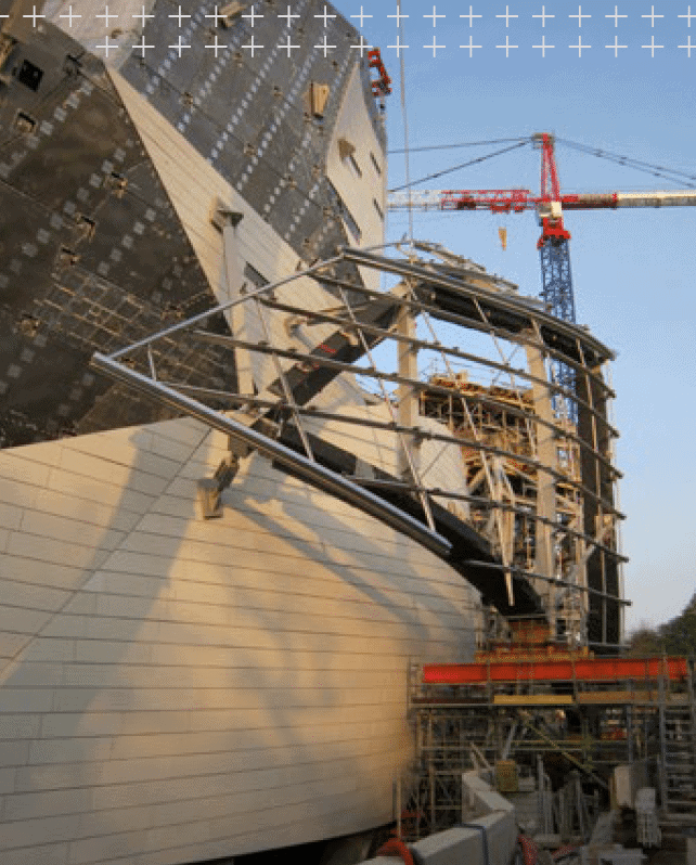
Looking at the very first sketches by Frank Gehry for Fondation Louis Vuitton, a new museum of contemporary art near Paris, the challenge of the endeavour is apparent. This is the kind of building that would not have been possible to construct without a comprehensive approach to BIM.
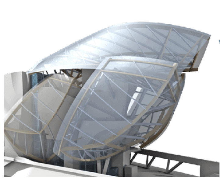
The museum is covered by glass sails, supported on stainless steel mullions upon a structural-steel and glulam main frame. The 12 sails form a cloudlike collection of canopies over the museum, with numerous curves and angles that reflect the surrounding trees and the Paris skyline.
Drawings Only for Fabrication
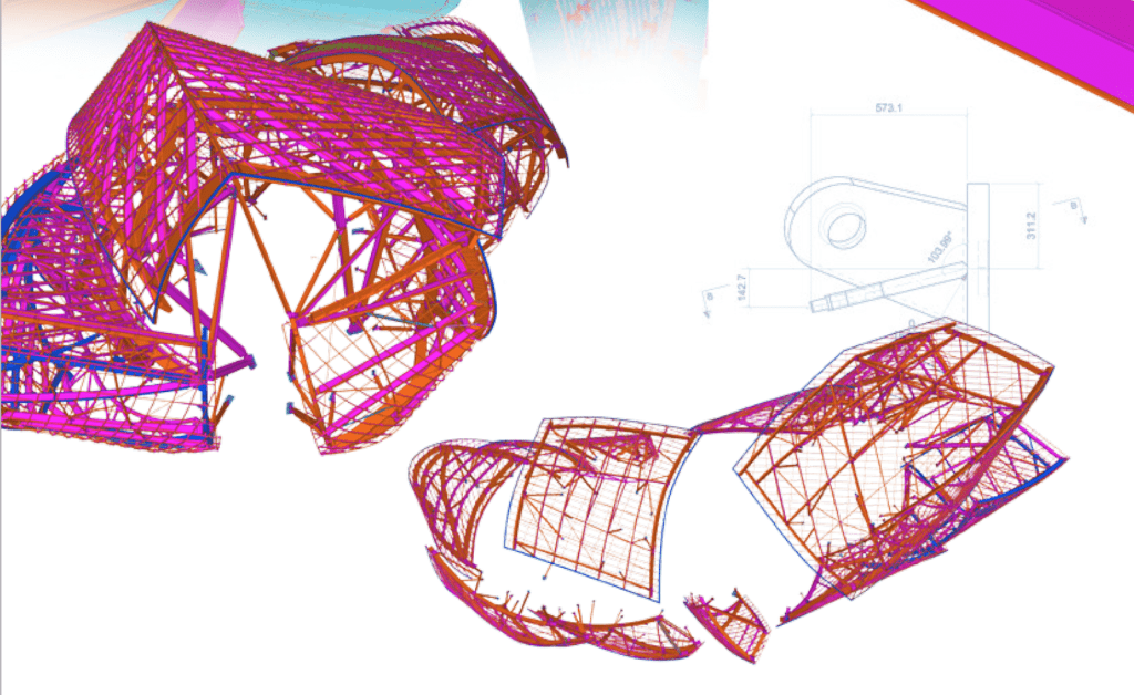
Steel fabricator Eiffage Construction Métallique contracted DBM Vircon to detail out the stainless steel mullions along with the glulam timber beams, glazing fixing plates, main frame and locating base frames.
“This was a unique BIM project, as the only actual drawings produced were those for the fabrication of parts and assemblies; all other information was provided between each project party from the 3D modeling process,” says Ian Belcher, UK Manager for DBM Vircon. “Our knowledge of how to get the most out of Tekla software, along with a client willing to work with us in providing the right information to all parties involved, was what made this project a success.”
Gehry Partners delivered 3D requirements via Digital Project™ to Eiffage for the structural design, then from this data the exchange files were issued to DBM Vircon for importing into Tekla for BIM collaboration and detailing.
The steel and timber model appears to float above the ‘Icebergs’, a concrete and steel framework covered with ceramic tiles.
“The supply of intricate drawings for fabrication had to be supplemented with electronic files and 3D data exchange files.”
Information for Automation From the Model
”The nature and intent of the project setting meant that the 3D interfacing between software tools had to be the only way forward,” says Belcher. Even with the supply of intricate drawings for fabrication, they had to be supplemented with electronic files and 3D data exchange files. On top of the CAM files for part fabrication via automated machines, DBM Vircon supplied 3D drawing files to aid setting out and quality controlling the node points.
The multiple curved glass surfaces of each sail meant that the stainless-steel mullion supports had to follow these curves and transoms’ spacer beams with varied end-plate rotations. Eiffage were able to automate the fabrication of these members with the aid of Tekla and DBM Vircon, as the required information could be created from the model to drive these machines.
Maintaining Tolerances from the Model
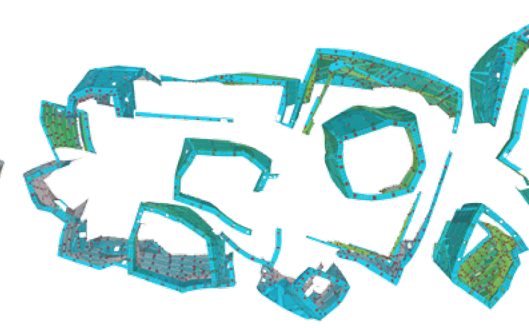
DBM Vircon imported the Digital Project data into Tekla via the industry standard IFC format for all items, and in addition, the drawing files for the centreline of all curved items. These files also indicated the change in radius of each member, with a point at the start, middle and end of the radius, which they were able to replicate into the Tekla model and onto fabrication drawings. Rolling drawings were dimensioned accordingly, but DBM Vircon also supplied CAM files for the rolling process.
Into the workshop, in addition to the normal CAM and 2D information, DBM Vircon supplied 3D drawings of all node blocks, so that during fabrication, the surveying equipment could be utilised in maintaining tolerances required for the project. Files were also supplied for the glulam manufacturer for use in the shaping and drilling of the timber beams.
“The only items that did not come directly from the Tekla model happened to be the twisted or corkscrewed glulam beams, which were supplied directly from the Digital Projects software,” Belcher explains.
Structural Core of Concrete and Steel
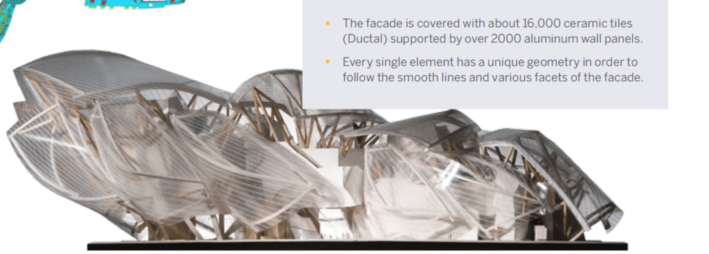
The museum’s structural core consists of a series of solid volumes called icebergs, which support the floating glass canopies covering the entire building. Structurally, the icebergs were designed as concrete and steel frameworks. The façade is covered with ca. 16.000 ceramic tiles. Every single element has a unique geometry in order to follow the smooth lines and various facets of the façade.
Over 2000 aluminum wall panels were designed and fabricated in order to obtain a support structure for the ceramic tiles. Each of these panels follows exactly the outside geometry of the façade surface and contains stiffening elements located underneath every joint between the ceramic tiles. The panels are connected to the steel or concrete structure by means of specifically designed spacers.
Automated Production of Panels
In order to keep the process for the aluminium cladding panels fabricated by Iemants Staalconstructies acceptable, both economically and technically, detailer company POUMA developed specific software tools, which resulted in a highly automated production process.
Starting with the input derived from the designers’ 3D models in Digital Project, all relevant geometrical data was imported into Grasshopper/Rhino. This software environment allowed the detailer to develop tools that could be used to semi-automatically generate each individual panel, including a large amount of detailing. Geometrically correct panels with joints and all necessary detailing were imported from Grasshopper into Tekla using open API, causing almost no additional fine-tuning for each unique panel.
Due to the complex geometry, building up workshop drawings demanded a specific approach. Using scribing lines, CNC-driven export files and control coordinates, the steel contractor was able to assemble the panels so that fabrication tolerances were limited to the minimum. Workshop drawings were fully automated, dimensioning and coordinate-list included. “Through this automated approach, different teams on different locations were able to collaborate simultaneously, following equal standards,” said Ilka Mans, Project Engineer at POUMA.
POUMA Engineers & Architects
Pouma is a specialised engineering and consulting company, founded in 2008 by a team of enthusiastic professionals, with a history of fabrication and construction design of complex building structures. www.pouma.be
Original Article written by Tekla can be read here.