“This is a bridge of the future – at over 500 ft, this project really advanced the state-of-the-art for tied arch design and construction” – Brian Kozy
The Hastings Bridge over the Mississippi River in Hastings, Minnesota, is a record breaker. Built as a replacement for the functionally obsolete Hastings High Bridge (built in 1950), the new 1,938ft long bridge with a 545ft main span is the longest freestanding tied-arch bridge in North America. The overall project was accelerated through MnDOT’s Chapter 152 Bridge Improvement Program following the I-35W bridge collapse. MnDOT identified this route as critical to the mobility and commerce of Minnesota because it carried the highest daily traffic volume of any two lane trunk highway in the state.
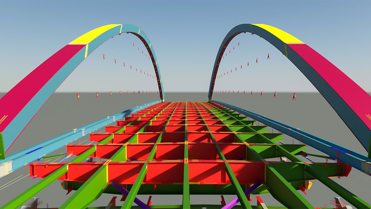
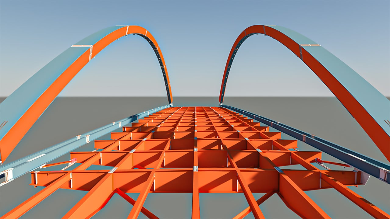
The structural steel bridge was constructed using design-build procurement and required accelerated bridge construction (ABC) technology to meet the demanding schedule and limit impacts on the travelling public. The tied-arch structural system is comprised of two freestanding vertical structural steel arch ribs with trapezoidal cross sections and variable depth. Post tensioning steel strands were used to resist the arch thrust and encased in cast in place concrete tie girders and knuckles. The structural steel floor system consists of a grid of steel floor beams, full depth longitudinal stringers and secondary longitudinal stringers all made composite with a cast in place concrete deck. The knuckles and deck are integral with the piers, creating a fully framed system. A network of structural strand hangers is used to suspend the floor system from the arch ribs. All structural tension members are load path redundant for fracture at any point in a single member or connection subject to tension under permanent loads and vehicular live load. Consequently, there are no fracture critical bridge elements on the structure. The structure was analyzed for fracture of all tension members using a 3D time history analysis to determine appropriate dynamic effects. The transverse floor beams and full depth longitudinal stringers form a grid floor system, which allows load transferring in both the longitudinal and the transverse directions. This structural steel grid forms a redundant system with the primary load path through the transverse floor beams. The full depth longitudinal stringers provide multiple supports, which minimize deflections from the potential fracture of a floor beam and significantly reduce the resulting fracture energy release and dynamic impact.
The design-build team determined very early that the traditional methods of erecting the arch offsite on high towers and floating it in over the piers was too risky due to the high center of gravity and variability of river water elevations, which could delay move in. Therefore, the team elected to erect the arch on land, transfer it onto barges with self-propelled modular transporters (SPMTs), float it in low, position it between the piers using a skid rail system and lift it into place with strand jacks on top of the piers.
The steel floor beams and longitudinal stringers were erected on land in the staging area by the river bank with temporary supports. A temporary tension tie system, consisting of two W36 sections to resist the thrust of each arch rib, was used to facilitate the erection and served to stabilize the floor system and support the formwork for the cast in place tie girder. A steel lifting connection served as a temporary knuckle connecting the arch rib with the temporary tie. Finally, the hangers were installed between the arch rib and the ends of each floor beam. The arch ribs were braced during erection, and the entire system was framed using the temporary rib bracing, floor system and the lower lateral bracing system.
After completing the steel member erection on land, eight 16-axle SPMTs were brought in and situated with two under each of the corners of the arch system. The vertical lifting ability of the SPMTs was used to lift each of the four corners of the arch in unison, bringing the arch off of its support towers and the floor system off the temporary supports. The total vertical lift was approximately 6 in. to account for the deflection of the arch and elongation of the tie as the arch picked up the weight of the floor system. The wheels of the SPMTs at one end of the arch were rotated 90° to allow them to roll with the elongation of the temporary tie girder. After a successful lift-off, the wheels were rotated back to prepare for the move down the slope to the river bank, while all the temporary supports and towers were taken down. The SPMTs under the comers at each end were connected together to act in unison for moving the arch system transversely down to the river bank and over a trestle onto barges. Water level monitors at each comer of the arch were used to check the slope between the ends of each arch and the SPMTs were adjusted vertically to maintain a constant slope between the arches and avoid twisting the floor system as they marched the arch down a 3.5% slope to the river and onto the barges.
One barge was positioned at each end of the arch to allow each 104-ft-wide end to roll onto the barge from one end toward the center until both sides of the arch were positioned in the center of the two barges. The barges were constantly monitored and re-ballasted as the SPMTs rolled each end of the arch onto the barges. The total move onto the barges took about 12 hours.
The arch was floated down stream to the bridge site and positioned adjacent to the piers. Due to the curve in the river bank and the south piers’ position on the river bank, the arch was skidded south off the south barge onto the river bank with a skid track system until it lined up with the horizontal skid rails that were positioned between the piers. Once in position on the south end, the support was transitioned from longitudinal to transverse skid shoes. The north end of the arch was unloaded off the barge onto the skid rails during the transverse slide with the help of SPMTs on the barge. Once positioned between the piers, the arch was ready for lifting.
The lifting frame supporting the strand jack system was anchored directly to the top of the pier. The strand jack system was connected to the arch system-lifting connection and hoisted 5 5 ft onto the top of the piers. Pier deflections were monitored and checked to ensure clearance after liftoff from the skid rails. Once in place, a support frame was moved into position under the temporary knuckle and the bridge was lowered into its final position. The lifting connection and support frame were cast into the permanent concrete knuckle. The concrete tie girder and knuckle were post-tensioned sequentially as the knuckle, tie and deck concrete were placed. To compensate for creep, shrinkage and shortening, the piers were jacked apart 6 in. before casting the knuckle, and the temporary arch bracing remained in place until the deck was cast. The deck was placed in a single pour, beginning at the center of the bridge. Hanger adjustments for geometry and stress were made by modifying the heights of the shim packs at each hanger. The float-in and lift process for the 3,300-ton arch steel structure was completed within a 48-hour window to limit the amount of time the Mississippi River navigation channel was closed.

Owner
Minnesota Department of Transportation, St. Paul
Designer
Parsons Corporation, Chicago
Contractor
Lunda Construction Company, Rosemount, Minn.
Steel Fabricator
Veritas Steel, Eau Claire, Wis.
Steel Detailer
DBM Vircon Services
Originally written in Modern Steel Construction Magazine June 2016 Issue
Read Full Article Here https://lsc-pagepro.mydigitalpublication.com/article/NSBA+2016+Prize+Bridge+Awards/2483512/302360/article.html


