
Paducah, Kentucky
Paducah, KY., has become home to a $95 million visually transparent, parallel chord truss bridge over the Tennessee River.
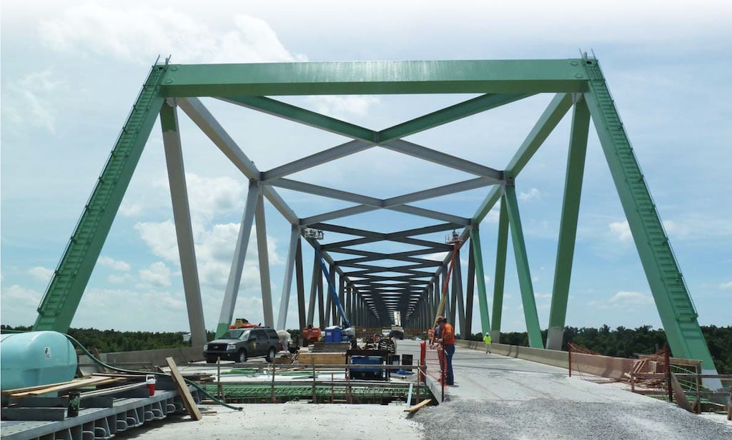
The Kentucky Transportation Cabinet (KYTC) recently replaced an aging, structurally deficient span of U.S. 60 in western Kentucky with a three-span, continuous Warren style through truss.
The KYTC selected URS Corp. and Stantec to design the new state-of-the-art steel truss superstructure, which features an aesthetically pleasing bridge that is not cluttered with the vertical members and sway bracing used in conventional truss designs. The new bridge features a 71ft wide deck with four driving lanes, a 4ft shoulder and a concomitant 5ft shoulder that will be designated as a bicycle lane.
The design of the new steel truss overcame various challenges arising from the demands of the long main span on a relatively shallow truss. These challenges were compounded by rigorous seismic loading on piers designed to accommodate a different structure. The design team chose to develop a solution that would not require retrofitting the existing foundations or piers.
Easier on the eye
Located just upstream from the Tennessee River’s confluence with the Ohio River, the truss connects U.S. 60 from Paducah to Ledbetter. The bridge it replaces, known as the George Rogers Clark Memorial Bridge, is located 2,200 ft downstream from the new site. When it opened to traffic in 1931, it was two lanes wide with no walkways or shoulders. Its continued deterioration resulted in a 3 ton weight restriction that was implemented in 2012, which limited bridge access to midsized pickups and cars and imposed severe limitations on communities and businesses that used the bridge regularly.
The design team was challenged to come up with a steel truss superstructure compatible with the ongoing construction of the piers. The designers also needed to take into account the public’s concerns by creating a structure with a less cluttered appearance. Local residents felt that the low hanging sway braces and vertical members made the bridge seem too closed in.
The 900ft main span of the bridge is one of the longest built for a constant depth truss, and it is believed to be the eighth longest continuous truss span in the world. The depth of the truss, a limit of 60 ft, challenged the design team to develop economical member proportions and connections. To achieve both the desired span length and truss depth, the designers incorporated a variety of innovative applications and approaches.
Combining efficient panel spacing, the creation of a lightweight truss design and detailing clean and compact connections together with steel fabricators, the project team determined the upper limit on fabricating and shipping economical member lengths. The panel spacing ended up being a function of the rolling length of the steel members and required plate thickness. The end product essentially created a series of variable length equilateral triangles that minimized the number of primary truss connections, significantly reducing detailing, fabrication and erection costs.
Special attention was given to providing clean and simple details in every aspect of the design, including secondary truss components. The upper and lower lateral bracing is made up of rolled sections, which simplifies the detailing and fabrication over built up sections. The lower lateral bracing consists of a diamond pattern that places the connections to the chords at mid panel instead of at the panel points, thus simplifying the gusset floor beam connections and providing lateral support to the compression flange of the steel floor beams at midspan.
The portal bracing also was eliminated at all intermediate locations, with only Vierendeel welded box end portals provided at each end of the truss. This 6ft deep box provides a visual and clear open entrance and exit to the bridge.
Such attention to detail resulted in an unusually lightweight steel truss. Not including the stringers, the steel weight of the truss skeleton is less than 100 lb per square foot of deck area. By contrast, some plate girder bridges less than 300 ft in span length have a greater weight of steel per square foot.
The depth of the truss, a limit of 60 ft, challenged the design team to develop economical member proportions and connections. To achieve both the desired span length and truss depth, the designers incorporated a variety of innovative applications and approaches.
Smaller, more compact
Navigable waterway requirements for the river governed the location of the supporting piers; however, this resulted in an undesirable and asymmetrical span arrangement. This produced a possible uplift condition due to live load in the continuous truss at the end of the shorter 400ft span. This situation was remedied by adding a monolithic concrete counterweight below the deck at the end of the span.
The 900ft span and relatively shallow 60ft constant truss depth resulted in the development of significant forces in the truss members and primary truss connections. Such forces must be resisted by a large number of bolts that can create large connections. The design team wished to limit the size of these connections for several reasons.
Compact connections help reduce secondary bending moments from developing in the members. Moreover, smaller gusset plates increase aesthetic appeal and minimize the unsealed areas of the chords. The size of the truss connections was reduced by economizing bolt use, utilizing double shear splice plates and specifying mill-to-bear surfaces at select connections.
The size of the gusset plates was reduced with an efficient use of bolts that included utilizing 1 1⁄8in. bolts (slightly larger than is customary), excluding threads from the shear planes and using staggered bolt patterns. The larger diameter bolts were specified for gusset connections because they made it possible to realize more capacity per square inch of gusset plate than smaller bolts.
However, the greatest reduction in the size of the gusset plates was achieved by the use of a staggered bolt pattern, which increased the capacity per square inch of each gusset plate by almost 75% as compared with a conventional square layout and gauge spacing. The careful detailing of the gussets lowered costs by reducing the size of the gussets, number of bolts and holes and degree of labor required for installation.
The lower chord connections included floor beam tie plates to transfer horizontal shear and to provide fixity in the floor beam connections for live load. Since the tie plate spans the interior gusset, the gusset height was limited to less than the depth of the floor beams. This initially created a problem because there was not enough real estate to provide the number of diagonal bolts required at the lower chord gusset connection.
This problem was addressed by utilizing double-shear splice plates where needed. The splice plates allowed the bolts connecting the diagonal to the gusset plate to act in double shear, reducing the number of bolts and thus the overall size of the gusset plates. The same concept was employed on the upper chord, though the gusset plate was not constrained to a particular depth at those locations due to the absence of steel floor beams.
What’s more, designers had to account for significant forces that developed in the diagonals and chords over the continuous piers. Required to accommodate large loads within the geometry of the lower chord connections with available plate sizes from the mills, the design team’s solution was to develop unique welded assemblies for the connections above the steel truss bearings.
Instead of using a standard gusset plate, the knuckle assembly consisted of a large weldment whose geometrical assembly was specified as mill-to-bear. Specifying the connections as mill-to-bear required tight fabrication requirements to be set. However, this allowed the design to greatly reduce the number of bolts in the lower chord to weldment attachments and ultimately reduce the size of the gusset plate.
Eliminating connections
An innovative maintenance free deck that eliminated all intermediate deck joints and resulted in a continuous 1,800ft deck also was designed. The underlying floor system is not susceptible to corrosion from water or de-icing salt leaking through the deck joints. Innovative though it was, the creation of this continuous deck was not without its challenges.
Differential temperature effects between the long concrete deck and supporting truss resulted in significant forces forming at the floor beam connections. This was alleviated by specifying a detailed stringer fixity plan and including a traction frame near the center of the structure to transmit longitudinal forces between the deck and truss skeleton. The traction frame—essentially a truss in the horizontal plane connecting the stringers, floor beams and lower chord—was used to reduce bending moments in the weak axis of the floor beams.
Isolation units
The seismic design in the potentially active New Madrid seismic zone—thus named for the southwest stretching zone’s origins in New Madrid, Mo. —presented a daunting challenge to accommodate the new steel truss on previously constructed piers without requiring any retrofits. The piers for the bridge were constructed based on the design of a different superstructure. The project scope included a re-evaluation of the previously selected earthquake design, the design of the truss bearings and evaluation of the as-built piers and foundations for the selected seismic demand.
Foundation forces resulting from a multimodal response spectrum analysis for the Maximum Credible Earthquake (MCE) design were evaluated at each pier for geotechnical and structural capacity of the supporting friction piles. The impact of potential scour of the foundations was considered in their stiffness and capacity calculations. Due to the extreme event nature of full calculated scour effects and earthquake loading, it is considered excessively conservative to include the full scour depths in the seismic analysis; therefore, a 50% scour level was assumed.
Lead core elastomeric seismic isolation bearings were used in the design of the structure. The basic concept of using isolation bearings is twofold. First, the fundamental period of the structure is increased to a lower seismic demand level. Secondly, the isolated modes have increased damping characteristics, which lower the seismic demand. For the Kentucky truss, the isolation bearings provide approximately 20% damping longitudinally and 30% damping in the transverse direction to the isolated modes of the structure. To the extent possible, the seismic isolation bearing design attempted to minimize impacts to the foundations and shift seismic demand away from the most susceptible foundations. By proportioning the seismic isolation bearings to essentially uncouple the truss from the piers, the already constructed piers could be utilized without requiring any structural retrofits.
The new visually transparent, 1,800ft long truss bridge has provided Paducah with a state-of-the-art structure capable of handling an increasingly heavy traffic load, preserving an integral corridor in western Kentucky’s transportation network.
First published in Roads & Bridges
Contributing Authors:
By Craig R. Klusman, P.E.
Donald N. Corda, P.E., S.E.
C. Tony Hunley, Ph.D., S.E.