
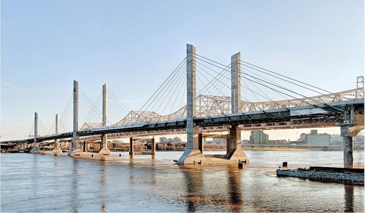
Connecting Louisville KY., with Jefferson IN., across the Ohio River
COWI North America Ltd. designed an innovative foundation system with an inherently flexible three-tower cable-stayed system and employed state of the art probalistic service life design to achieve the specified 100-years of life.
Project Information:
Project Name: Abraham Lincoln Bridge
Location of Project: Connecting Louisville KY with Jefferson IN across the Ohio River
Completed by: 2016
Project Description:
The new Abraham Lincoln Bridge connects downtown Louisville, Kentucky, to Jeffersonville, Indiana across the Ohio River. This landmark project was a collaborative effort between Kentucky Transportation Cabinet (KYTC) (Owner), Walsh Construction (Design-Build Contractor), Jacobs Engineering Group (Prime Consultant), and COWI North America Ltd. (COWI) (formerly Buckland & Taylor) (Subconsultant).
The purpose of this project was to improve connectivity between the two states and alleviate traffic on the existing JFK Bridge.
As Project Owner, KYTC had a set vision of the bridge type and arrangement, which included:
- 3 towers and 4 cable stay spans
- Bridge spans and tower height above deck symmetric about the center tower
- Center tower taller than two side towers
- Towers unbraced (no crossbeams) above deck level
- Five-sided tower leg section (similar to baseball home plate)
- 100-year service life
Jacobs Engineering Group hired COWI as engineer of record for the cable-stayed bridge. COWI also provided Walsh Construction with detailed erection engineering, temporary works design and construction services (RFIs, submittals, etc.).
Innovations
Designed under unique geo-technical conditions, the steel bridge uses an innovative foundation system with an inherently flexible three tower cable-stayed system. The challenging subsurface conditions at the site included highly-variable depths to bedrock at each end of the bridge. This resulted in a stiffness contrast for the structure that required careful consideration of foundation axial capacity and lateral stiffness in order for the bridge to remain technically and economically feasible.
The three-tower cable stayed main span is 640 m (2,100 ft) long. The two middle spans are 228m (750ft) and the two side spans are 92m (303ft). The center tower extends 59m (195ft) and the side towers extend 44m (145ft) above the steel deck. All three towers have twin reinforced concrete vertical legs in a pentagon shape with no cross beams above the deck. Two planes of stay cables fan out from the tower tops and are anchored to the exterior of the steel superstructure. The substructure consists of three tower foundations on drilled shafts placed in the river, and two anchor piers with drilled shafts, at each end of the bridge.
This is the first major cable supported bridge where a single line of large diameter drilled shafts was used for each tower foundation. The combination of three-tower arrangement and single line of drilled shafts for each tower foundation created a very flexible system.
However, using the single row of drilled shafts did result in high geo-technical and structural demands on the drilled shaft foundations, both under critical unbalanced erection loads during the erection of superstructure and under governing live and wind loads. Variable limestone depths on both the Kentucky and Indiana sides created the severe foundation stiffness contrasts that affected the load transfer from the superstructure to the substructure and the location of the bearing fixity. Throughout the project, the design team continuously pushed the boundaries to address these technical challenges. In order to verify the ambitious foundation concept, a record setting Osterberg-Cell load test with an applied load of 36,333 tons to the test shaft was conducted and Statnamic lateral load testing was performed to verify the lateral stiffness of the drilled shaft socketed in limestone.
Project Solutions and Achievements
COWI developed the following structural design solutions for the towers:
-
- Single row of (4) 12′ diameter shafts, which led to:
- Reduced number of shafts
- Reduced foundation construction cost and schedule
- Minimize risk of debris collection
- Minimize disturbance to river flow
- Maximize navigation clearances
- Optimized stay cable and floor beam arrangement
- Longitudinal restraint at Tower 5 only
Outstanding Engineering Achievements
COWI bridge engineers successfully developed the following engineering solutions:
- Single line of shafts concept
- Bridge erection scheme working with a single line of shafts
- Wind fairing system
- Shaft 3R-2 repair
Site Considerations and Other Challenges
As engineer of record and erection engineers, COWI managed a number of construction related challenges including:
- Drilled shaft design for Towers 3R and 4R were governed by erection loads because of the single line of shafts configuration
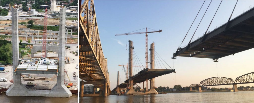
- Temporary towers were constructed to limit unbalanced loading during superstructure erection
- Tight restrictions on unbalanced loads in superstructure erection to prevent foundation overload
- Tight tolerances for installation of drilled shafts
- Shaft 3R-2 construction
- Cofferdam demolition at Tower 3 (leaning tower)
- Steel boxes fabrication (out of tolerance)
3D Modeling
COWI developed an extensive 3D modelling of the reinforcing steel in the concrete towers and foundations as the reinforcing steel had many very congested areas. This modelling allowed Walsh to confidently and successfully build the complex towers.
The tie down devices were also modelled to show how they could be effectively constructed and to assure proper fit-up.
Complexity
Challenging subsurface conditions at the site included highly-variable depths to bedrock at each end of the bridge. This resulted in a stiffness contrast for the structure that required careful consideration of foundation axial capacity and lateral stiffness in order for the bridge to remain technically and economically feasible.
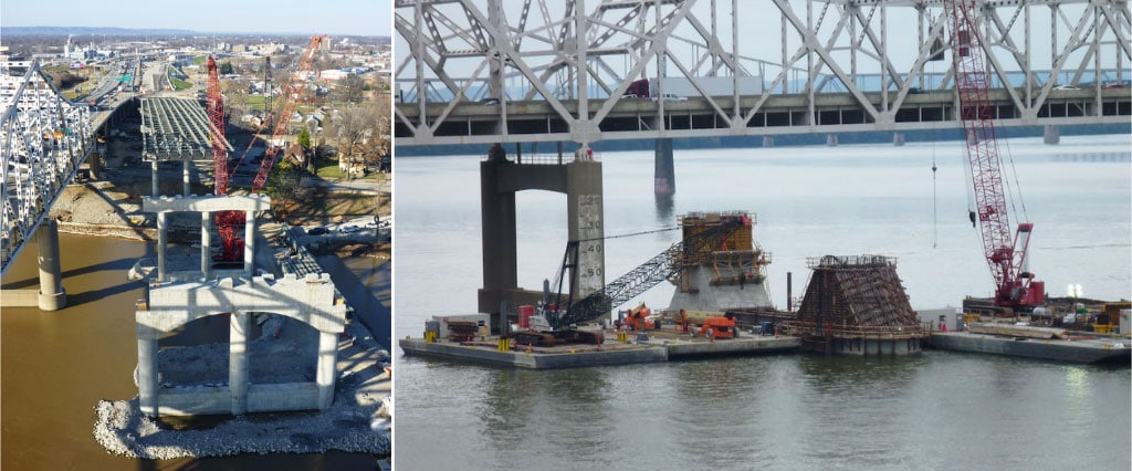
Drilled shafts support the three main towers and the two anchor piers. Each tower foundation is supported by a single row of four 12 ft (3.7 m) diameter drilled shafts socketed into limestone. The selected foundation system reduced the foundation installation time and accelerated the overall bridge construction schedule, which was a vital component for this design-build project.
However, using the single row of drilled shafts did result in high geotechnical and structural demands on the drilled shaft foundations, both under critical unbalanced erection loads during the erection of superstructure and under governing live and wind loads. Variable limestone depths on both the Kentucky and Indiana sides created the severe foundation stiffness contrasts that affected the load transfer from the superstructure to the substructure and the location of the bearing fixity. Throughout the project, the design team continuously pushed the boundaries to address these technical challenges.
In order to verify the ambitious foundation concept, a record setting Osterberg-Cell load test with an applied load of 36,333 tons to the test shaft was conducted and Statnamic lateral load testing was performed to verify the lateral stiffness of the drilled shaft socketed in limestone.
Social and/or Economic Benefits
The Abraham Lincoln Bridge improves connectivity between Louisville (Kentucky) and Jeffersonville (Indiana). This new route reduces stress and strain on the existing JFK Bridge, thereby decreasing its rate of wear and fatigue. The Abraham Lincoln Bridge will provide a memorable, aesthetically pleasing, structure designed to carry increased traffic into the future.
From the start, the project had significant public involvement beginning with the feasibility study, public open houses throughout the design-build process, and a grand opening at the end of the project. As engineer of record and erection engineer, COWI designed the Abraham Lincoln Bridge to meet the public’s requirement. As part of the grand opening celebration, a public walk was held with over 50,000 people in attendance. Each participant received a commemorative medallion.
Close collaboration between the contractor and the design engineers led to an innovative, cost-effective design that achieved the Owner’s stringent technical requirements.
COWI developed cost-effective design solutions that included:
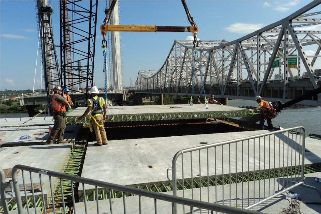
- Composite steel deck and precast panels, with CIP in-fills and post-tensioning
- Precast slabs eliminated the need for cofferdams at Towers 4 and 5
- Precast slabs and tubs were used for the construction of pier 2 and 6 (saved forming time and cost)
- Composite section design for Shaft 3R-2 retrofit (steel beam and reinforced concrete).
- Environmental and Sustainability
COWI successfully completed the project’s sustainability requirements of 100-year service life design. The Abraham Lincoln Bridge in one of the first major steel bridges in North America where a rational durability study was explicitly performed, and incorporated into the design process.
The concrete components of the radiating substructure and superstructure were designed for a 100-year service life. (Tower 3 shown)
The Abraham Lincoln Bridge has been designed to withstand a significant terrorist threat, cable loss, high fracture toughness and a 100-year service life design. COWI engineers applied a “ruthless approach” to make every aspect of the project durable. It can handle significant ship collision, a high amount of blast protection and has significant redundancy. The specifications required non-replaceable elements of the steel bridge to have a 100-year service life. COWI developed a corrosion protection plan that provided the bridge a 90 percent probability of meeting or exceeding the prescribed service life. It is anticipated the life span of the bridge will surpass 100 years.
The innovative tower foundation is supported by a single row of four 12 ft (3.7 m) diameter drilled shafts socketed into limestone. This foundation system minimizes the dimension perpendicular to the river flow and maximizes the main span navigation clearances. As a result, environmental concerns are addressed by minimizing disturbance to river flow and the risk of debris accumulation.
Meeting Client Needs
The Abraham Lincoln Bridge was completed on an aggressive design and construction schedule.
The design-build contract was awarded in December, 2012, and the fast-paced design commenced in January 2013. Construction of the drilled shaft foundations began in the fall of 2013 and the bridge opened to traffic on December 6, 2015, slightly ahead of schedule.
Collaboration and positive communication were keys to the success of this project. The project management team fostered a positive and constructive attitude at all times. Close collaboration developed between Walsh and COWI, and KYTC and Jacobs provided clear communication throughout the project. COWI also received prompt resolution of design and construction issues with Owner’s Engineer (Baker) and Design/Build Team’s Independent Checker (IBT).
Close collaboration between the contractor and the designer engineers led to an innovative, cost-effective design solutions that achieved the Owner’s stringent technical requirements.
KYTC’s bridge type and arrangement requirements included:
- 3 towers and 4 cable stay spans
- Bridge spans and tower height above deck symmetric about center tower
- Center tower taller than two side towers
- Towers unbraced (no crossbeams) above deck level
- Five sided tower leg section (similar to baseball home plate)
- 100-year service life
COWI developed the following structural design solutions:
- Single row of (4) 12′ diameter shafts
- Optimized the stay cable and steel floor beam arrangement
- Developed a longitudinal restraint at Tower 5 only
A unique combination of materials helped save time and costs.
- Composite steel deck and precast panels, with CIP in-fills and post-tensioning
- Precast slabs eliminated the need for cofferdams at Towers 4 and 5
- Precast slabs and tubs used for the construction of pile caps/connecting beams
- Composite section design for Shaft 3R-2 retrofit (steel beam and reinforced concrete).
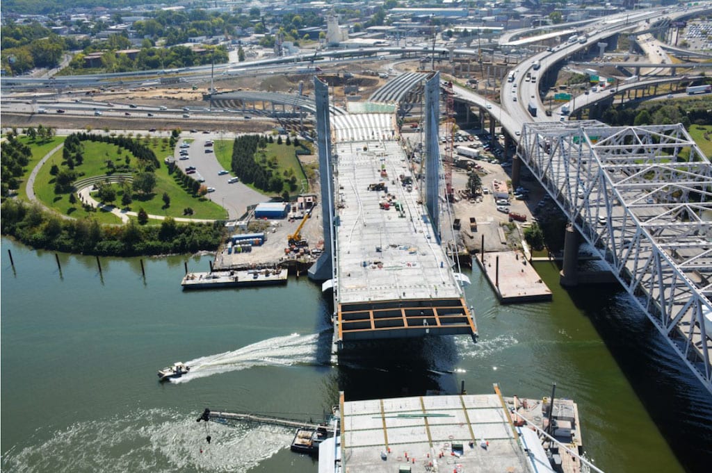
The gap is almost bridged at Span 3, Tower 3 to Tower 4.
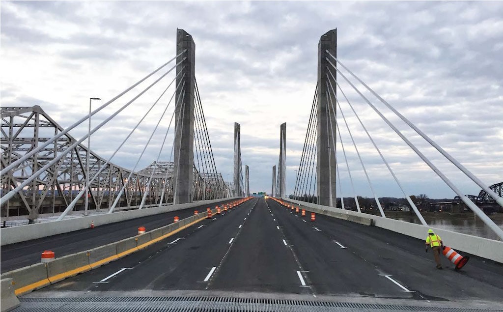
Looking north, Bridge ready for traffic, temporary configuration. (photo courtesy of Walsh Construction)
The Abraham Lincoln Bridge opened to traffic in December 2015, 4 months ahead of schedule. The project reached final completion in December 2016.
Prime Consultant: Jacobs Engineering Group
Other Consultants involved: International Bridge Technologies (Independent Check), Michael Baker International (Owner’s Engineer)
Contractor: Walsh Construction Company (Design-Build)
Detailer: DBM Vircon, New Westminster, B.C., Canada
First published by COWI