Elevator guiderail support tube including its connection to steel
Floor and roof opening frames
BRB Brace stick modelling and connection to primary steel columns and beams
Beam web penetrations
Entry canopy roof framing
Screenwall framing
Cooling tower support frame
Drive through canopy framing
Cafeteria framing beams and columns
Slab edge support/pourstop bent plates and angles (non gage)
Sloped deck/roof support bent plate at supporting beams
Slab/Deck support angle and plates, kicker, outriggers, braces and hanger angles attached to structural steel frame
Bent plate field/shop welded to beams
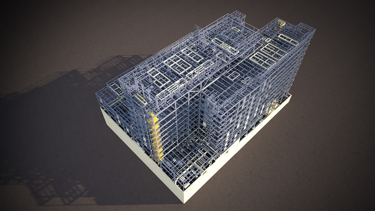
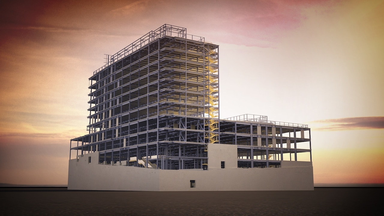
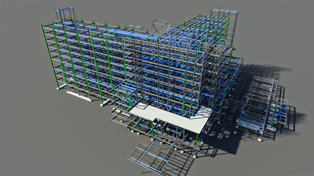
Cathedral Hill Hospital Project Highlights & Challenges:
The project was delivered within the clients demanding project schedule due to multiple changes to the original design.
As is typical with an OSHPD project, all missing information & non typical connections need to be approved & the design documents need to be updated accordingly. More than 650 RFIs were issued to make sure missing information and non-typical details will be reflected in future design drawing packages & consequently the model.
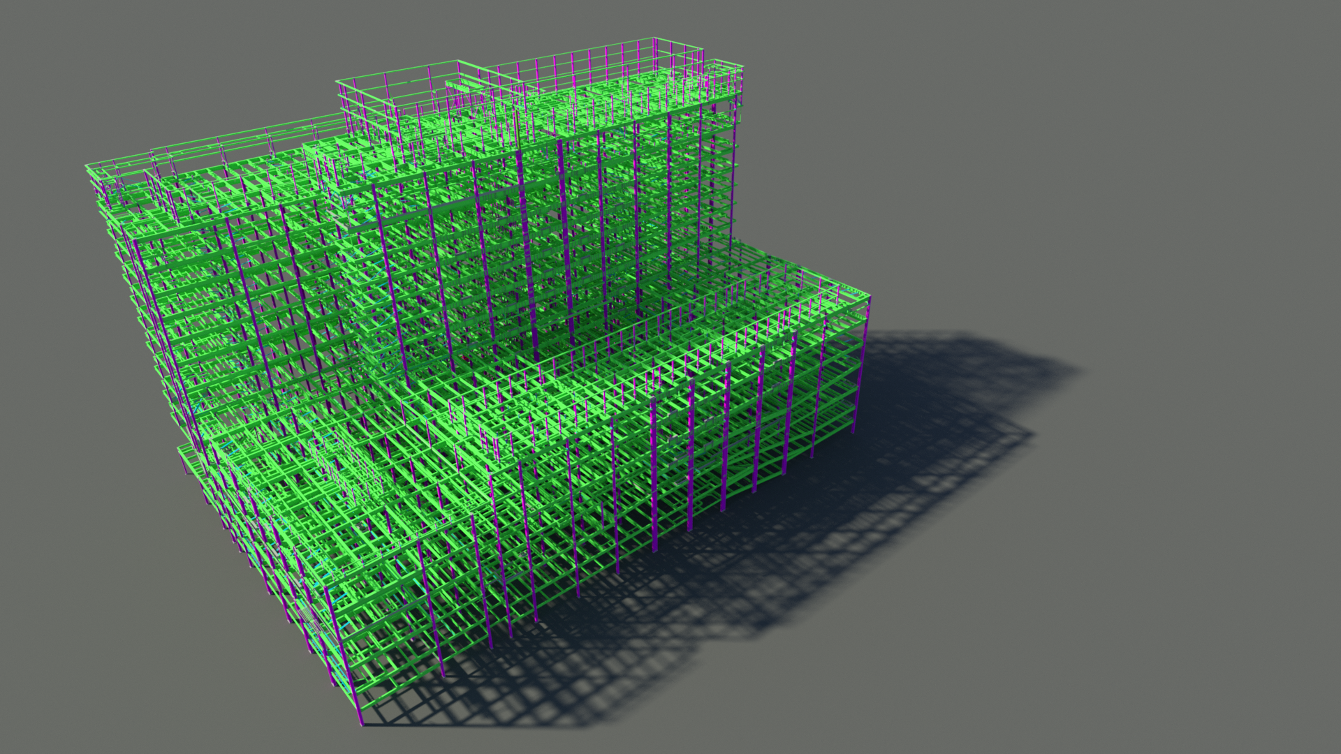
Model coordination for beam web penetrations: There are three types of beam web penetration we had to consider for this project. First are the duct beam penetrations which are mostly shown on the design drawings. Second are the plumbing beam penetrations and third are the Fire Protection (FP) beam penetrations. Plumbing and FP beam web pens are shown in IFC/3D dwg files supplied by the GC. The challenge is to make sure everything is modeled and that the Tekla model matches with the latest IFC/3D dwg model. Total beam web penetrations for this job were more than 3500.
Protected Zone for the SLRS moment beams – There are instances where the beam connections or deck supports are at the SLRS moment beam protected zone
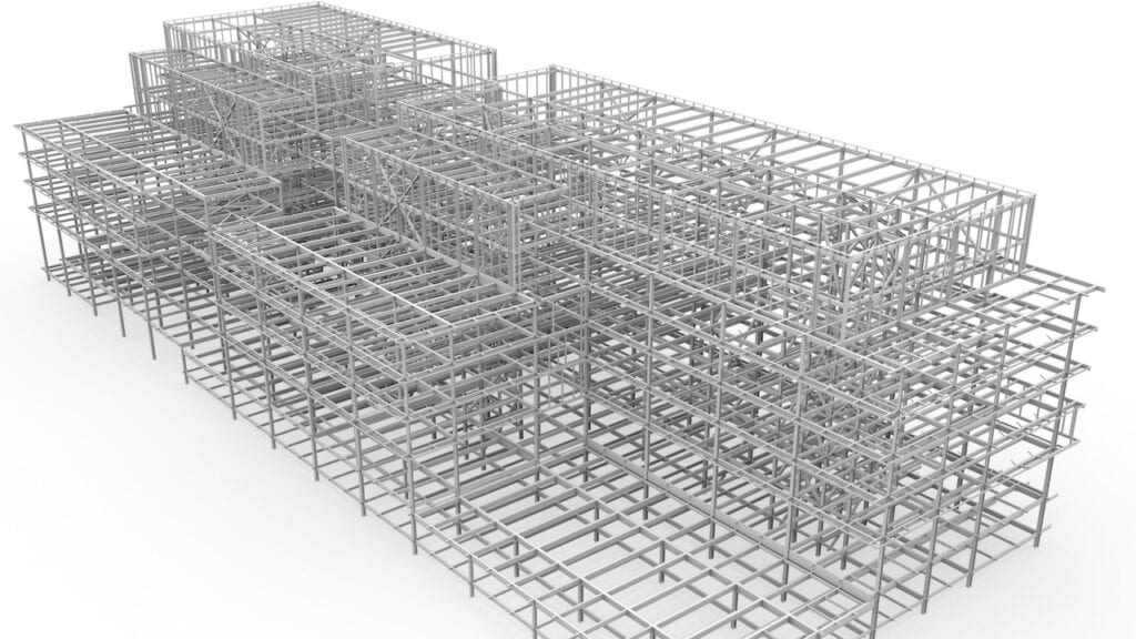
Deck Coordination: This project has a wide range of depressed and sloping slabs including ramps which has meant extensive coordination with the deck supplier has been carried out to ensure all deck support steel has been covered in the structural steel model
Damper Connections and Stiffeners: Due to the close spacing of the damper stiffeners, making sure the beams are erectable has been a challenge. This has led to extensive coordination during the 3D model review to ensure no issues occur in the field.
Column Lifting Lugs: At the lower levels of the structure some of the structural steel columns had the cage rebars attached which meant lifting lugs had to be designed accordingly.